Can resistors also have electrostatic capacity? Will resistors be damaged by static electricity? Many people may have doubts, but this article will introduce the electrostatic capacity of resistors as a starting point.
In daily design, we pay great attention to the electrostatic protection design of semiconductor devices, but rarely pay attention to whether resistors need electrostatic protection and whether resistors can also be damaged by static electricity and fail. The answer is yes, otherwise this article would be meaningless.
There are three models of static electricity HDM: human body model; MM: Machine model; CDM: Device discharge model. For the convenience of analysis, this article only selects a human body model as the research. The following is the electrostatic discharge model and discharge waveform of the human body model (refer to ISO10605).
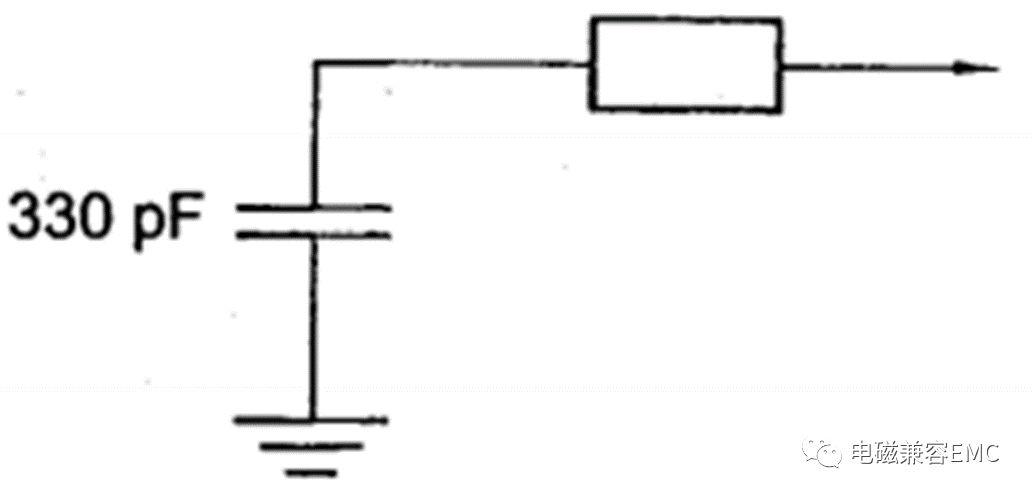
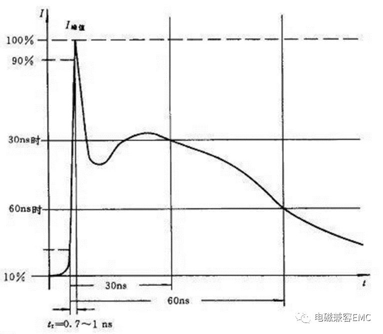
Figure 1. Human body model and discharge waveform
Firstly, let's define what failure is. There are three failure modes for resistors: open circuit, short circuit, and drift. If any one of them occurs, it is identified as failure, especially if the drift exceeds the specification calibration.
Firstly, let's determine several important parameters of resistance: voltage, current, rated power, and pulse power. I don't think I need to elaborate on the first three, but I will focus on the pulse power. Figure 2 shows the pulse power parameters of a 0603 resistor, including single pulse and repetitive pulse power.
Taking a ± 8kV human body model as an example: the electrostatic discharge time is in the ns level, refer to Figure 1 for details. The minimum time parameter given by the pulse power of the resistor in Figure 2 is 1us (10-6), and the difference is not particularly significant. Here, it can be assumed that the pulse power that the resistor can withstand is 70-90 times the rated power. (Note: The resistance of different processes is different, and this is a specific analysis for targeted purposes)
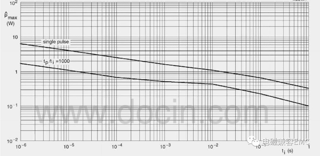
Figure 2.0603 Pulse Power of Resistance
Assuming the resistance of the port is 10K to ground, the actual pulse power that the resistance can withstand is:
Pesd=8000V*8000V/10K=6400W >> 90*PR=9W
There is a risk of resistance failure, with a typical failure being resistance drift. So don't think that the resistor discharge port can be worry free, but in fact, the risk is very high, and it is necessary to pay attention to and add certain protective measures during design. It should be ensured that the pulse power of the resistor can withstand the highest electrostatic discharge power.
EMC Rectification Tips:
1、 Differential mode interference and common mode interference
Differential mode interference: It exists between the L-N lines, where current enters from L, flows through the positive terminal of the rectifier diode, then through the load, passes through the thermal ground, reaches the rectifier diode, and then returns to N. On this path, there are high-power devices with high-speed switches and diodes with extremely short reverse recovery time. The high-frequency interference generated by these devices will flow through the entire circuit and be detected by the receiver, resulting in conduction exceeding the standard.
Common mode interference: Common mode interference is caused by parasitic capacitance between the ground and the equipment cable. High frequency interference noise will pass through this parasitic capacitance, generating common mode current between the ground and the cable, resulting in common mode interference.
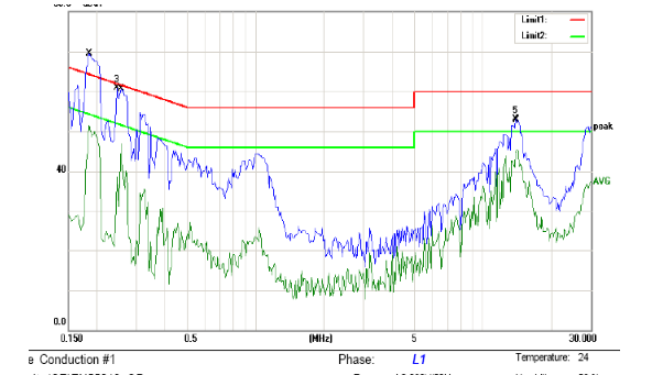
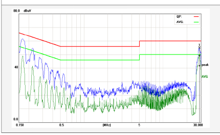
The following figure shows the conducted FALL data caused by differential mode interference. The front-end of the test data exceeds the standard, which is caused by differential mode interference:
The following figure shows the EMI principle of switch mode power supply:
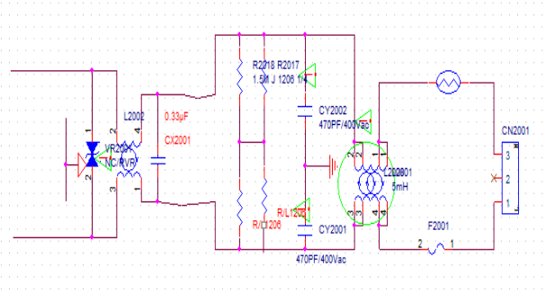
In the figure, CX2001 is a safety film capacitor (which appears as an open circuit when the capacitor is broken down or damaged). It spans between the L and N lines, and when the current between L-N flows through the load, it will bring high-frequency noise into the circuit. At this point, the function of the X capacitor is to form a circuit between the load and the X capacitor, allowing the high-frequency current to be diverted and consumed in the circuit without entering the mains power. That is, the short-circuit AC current through the capacitor prevents the interfering circuit from being connected to the outside.
Rectification measures for differential mode interference:
1. Increase the capacitance value of X capacitor
2. Increase the inductance of common mode inductance, utilize its leakage inductance, and suppress differential mode noise (because there are several winding methods for common mode inductance, such as double wire parallel winding or double wire separate winding, regardless of which winding method, due to loose winding, differences in wire length, etc., leakage phenomenon will definitely occur, that is, the magnetic field lines generated by one coil cannot completely pass through the other coil, which causes induced electromotive force between L-N lines, equivalent to connecting an inductor in series between L-N)
The following figure shows the common mode interference test FALL data:
The parasitic capacitance between the power cable and the ground creates a loop for common mode interference, and the interference noise flows through this capacitance to the ground, forming a common mode interference current between the LISN cable parasitic capacitance ground, which is detected by the receiver and leads to conduction exceeding the standard (this can also explain why some motherboards pass through without grounding during conduction testing, and a ground wire exceeds the standard). In USB mode, when not grounded, the current loop can only pass through the L-diode load hot ground LED-N, and the common mode current cannot return to the LISN. The noise detected by the LISN is small, while when the cold ground of the motherboard is directly connected to the ground, there is a loop between the cable and the ground. At this time, if the common mode noise is not absorbed by the front-end LC filtering circuit, it will cause conduction exceeding the standard.)
Rectification measures for common mode interference:
1. Increase the common mode inductance
2. Adjust the LC filters on L-GND and N-GND to filter out common mode noise
3. The motherboard should be grounded as much as possible to reduce the impedance to ground, thereby reducing the parasitic capacitance between the cable and the ground.
2、 The sources of electromagnetic compatibility interference for the product include:
1. The switching circuit of the equipment switch power supply: the main frequency of the disturbance source ranges from tens of kHz to hundreds of kHz, and the high-order harmonics can extend to tens of MHz.
2. The rectification circuit of equipment DC power supply: the upper limit of the frequency of the power frequency rectification noise of the power frequency linear power supply can be extended to several hundred kHz; The upper frequency limit of high-frequency rectification noise in switching power supplies can be extended to tens of MHz.
3. Brush noise of DC motors in electric equipment: The upper limit of noise frequency can be extended to several hundred MHz.
4. The operating noise of AC motors in electric equipment: high-order harmonics can extend up to tens of MHz.
5. Disturbance emission of variable frequency speed regulation circuit: The frequency of the disturbance source in the switch speed regulation circuit ranges from tens of kHz to tens of MHz.
6. Switching noise during device operation: The upper frequency limit of noise generated by mechanical or electronic switch actions can extend to several hundred MHz.
7. Electromagnetic interference of crystal oscillators and digital circuits in intelligent control devices: The main frequency of the interference source ranges from tens of kHz to tens of MHz, and high-order harmonics can extend to hundreds of MHz.
8. Microwave leakage of microwave equipment: The main frequency of the disturbance source is GHz.
9. Electromagnetic disturbance emission of electromagnetic induction heating equipment: The main frequency of the disturbance source is several tens of kHz, and high-order harmonics can extend to several tens of MHz.
The local oscillator and its harmonics of the high-frequency tuning circuit of 10 TV electroacoustic receiving equipment: the main frequency of the disturbance source ranges from tens of MHz to hundreds of MHz, and the high-order harmonics can extend to several GHz.
11. Digital processing circuits for information technology equipment and various automatic control devices: The main frequency of the disturbance source ranges from tens of MHz to hundreds of MHz (with internal frequency doubling reaching several GHz), and high-order harmonics can extend to tens of GHz.
 en
en