When it comes to EMC of switching power supplies, most people may first think of measures such as adding filtering devices, absorbing circuits, and optimizing layouts. However, in automotive electronics design, it is possible to design and consider the frequency of the switching power supply. So how to choose the frequency of the switching power supply?
1. First, let's take a look at a classic Fourier transform equation:
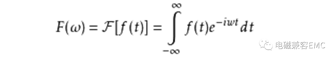
In our design, F (t) is a function of the switching frequency and time of the switching power supply. The time-domain waveform of the switching frequency of the switching power supply is shown on the left in Figure 1, and the frequency-domain waveform is shown on the right in Figure 1. We can observe that the switching frequency in the time domain remains constant, but it corresponds to different amplitudes at various frequency points in the frequency domain.
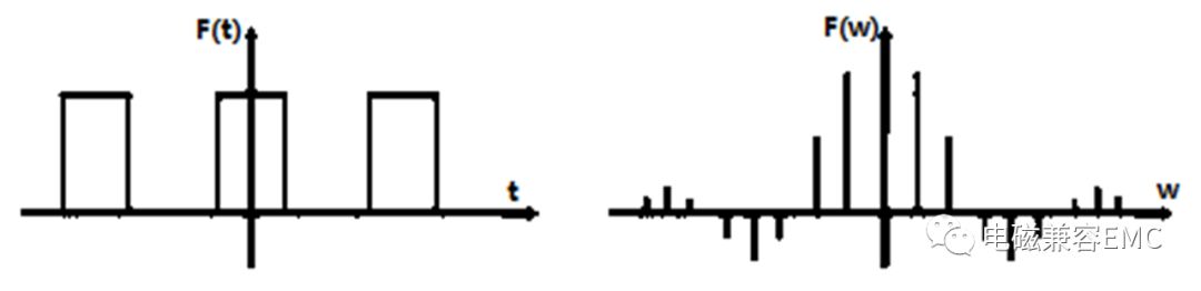
Figure 1. Time domain and frequency domain correspondence of Fourier transform
Because the harmonics in periodic square waves are the most abundant, decomposing the Fourier series of periodic square waves, as shown in the following equation, reveals that square waves are composed of periodic sine or cosine fundamental waves plus multiple harmonics. The energy of the fundamental wave is the highest, then decreases in sequence, and is infinite.

2. After analyzing the waveform, how can we correspond it to our design? Our engineering designers emphasize the importance of applying what we have learned. Figure 2 shows the radiation emission test results of a certain product GB18655. We can find that some of the limit values in the standard are blank, which are not required by the standard (emphasis)!
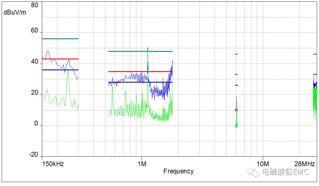
Figure 2. Results of GB18655 emission test for a certain product
The conclusion we can draw from the first part is that the amplitude of the fundamental wave is the largest. Therefore, when designing, we need to select the frequency of the fundamental wave with the highest energy in the standard blank, which is between 0.3M-0.53M and 1.8M-5.9M. This is the most effective frequency selection method, once the first step is done correctly, the rest can be easily solved. The same method can also be used in other standards to avoid areas with low limit values. (End)
EMC Rectification Tips:
1、 Differential mode interference and common mode interference
Differential mode interference: It exists between the L-N lines, where current enters from L, flows through the positive terminal of the rectifier diode, then through the load, passes through the thermal ground, reaches the rectifier diode, and then returns to N. On this path, there are high-power devices with high-speed switches and diodes with extremely short reverse recovery time. The high-frequency interference generated by these devices will flow through the entire circuit and be detected by the receiver, resulting in conduction exceeding the standard.
Common mode interference: Common mode interference is caused by parasitic capacitance between the ground and the equipment cable. High frequency interference noise will pass through this parasitic capacitance, generating common mode current between the ground and the cable, resulting in common mode interference.
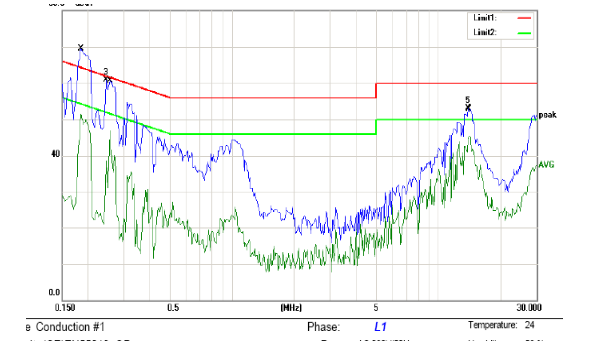
The following figure shows the conducted FALL data caused by differential mode interference. The front-end of the test data exceeds the standard, which is caused by differential mode interference:
The following figure shows the EMI principle of switch mode power supply:
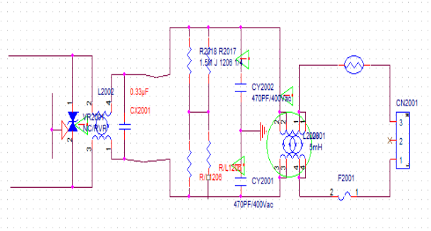
In the figure, CX2001 is a safety film capacitor (which appears as an open circuit when the capacitor is broken down or damaged). It spans between the L and N lines, and when the current between L-N flows through the load, it will bring high-frequency noise into the circuit. At this point, the function of the X capacitor is to form a circuit between the load and the X capacitor, allowing the high-frequency current to be diverted and consumed in the circuit without entering the mains power. That is, the short-circuit AC current through the capacitor prevents the interfering circuit from being connected to the outside.
 en
en